01
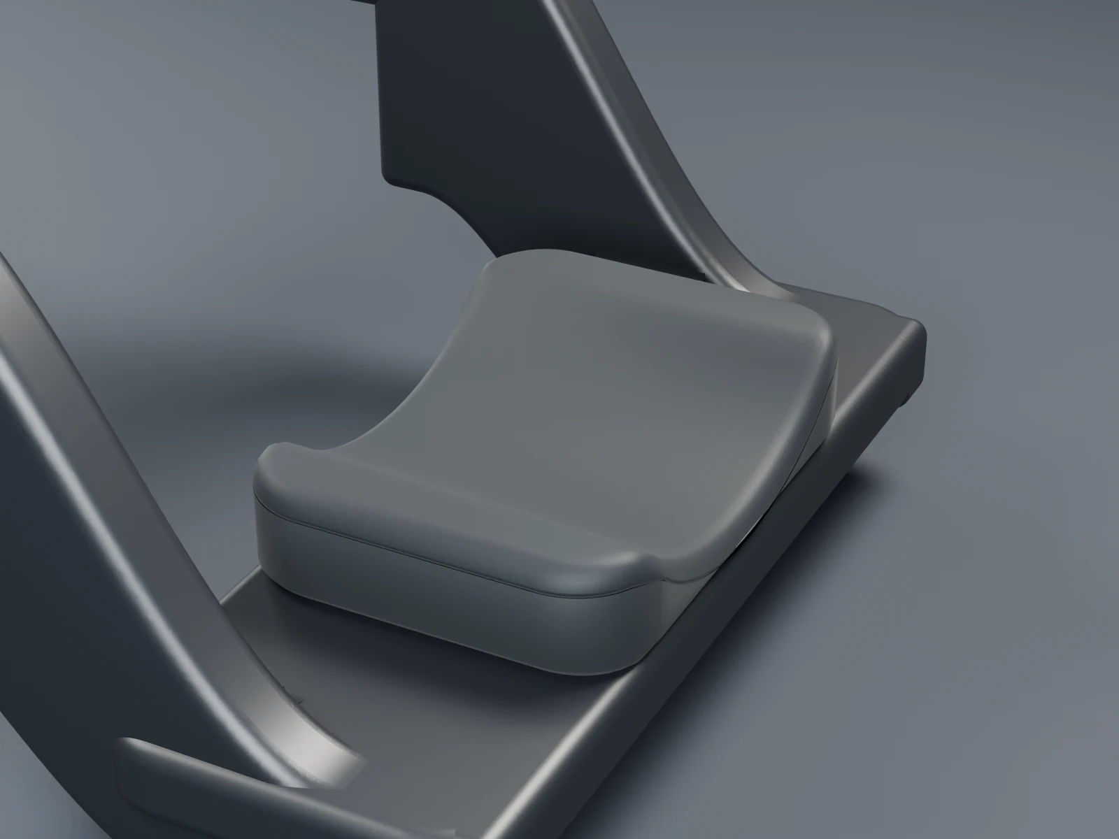
Support at the distal forearm.
A rounded contact surface with separate foam and upholstery. The pad meets only the distal forearm, leaving the back of the hand and wrist joint free.

STOAD / SIDEHEV / CABLE HANDLE V3
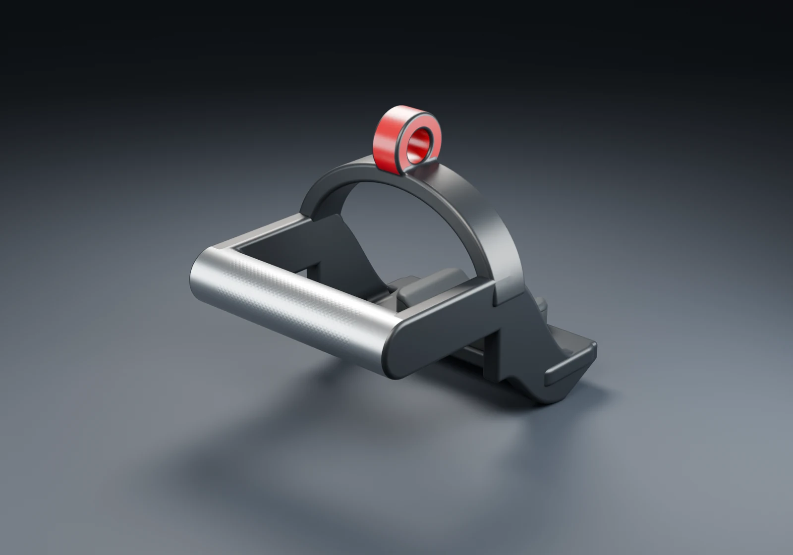
A cable handle combining a firm grip with distal forearm support. Developed for lateral raises and underhand pushdowns. Its effect on load sharing requires testing.
Prototype V3 · In development · Not for sale
A FIRM GRIP. FOREARM SUPPORT.
Being developed for lateral raises and underhand pushdowns, with support only at the distal forearm. The aim is to transfer more load through the support while maintaining a firm grip.
THE WHOLE MOVEMENT / SCHEMATIC
Low cable. The figure shows shoulder movement and cable direction. See the hand placement in the close-up below.
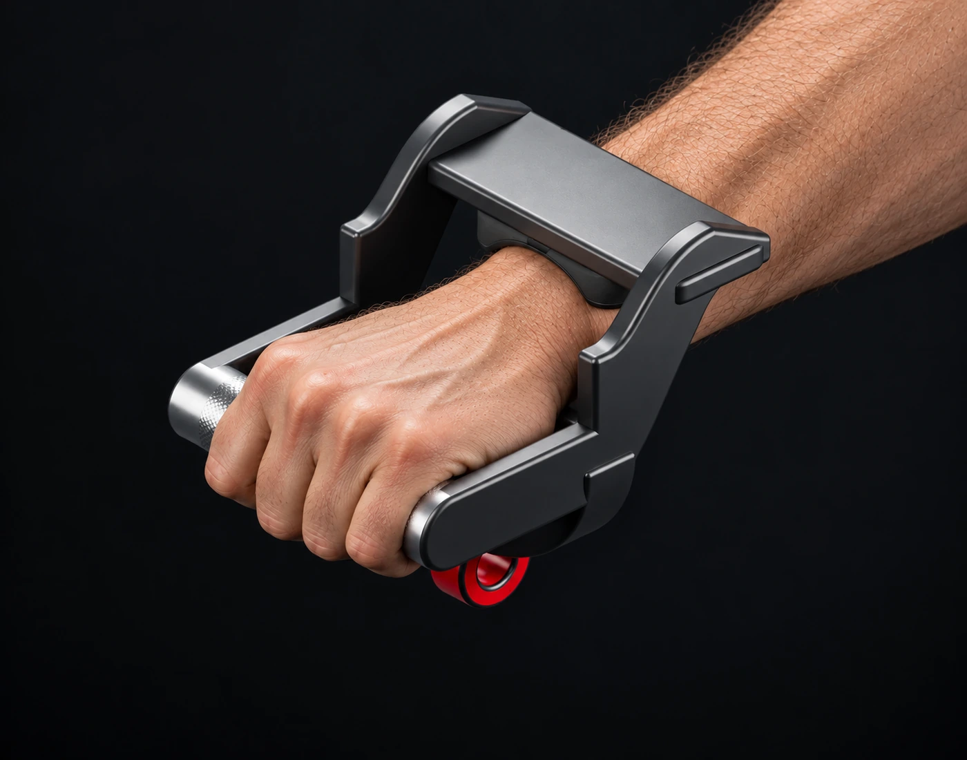 Lateral raise
All four fingers wrap around the bar tightly. The thumb opposes them. Keep a firm, closed grip throughout the movement.
The pad meets the distal forearm, beyond the wrist joint. The back of the hand stays free. The same forearm side meets the support in both main exercises.
The cable pulls towards the low pulley. Keep hand and forearm aligned; support load sharing and wrist moment require measurement.
EVERY DETAIL
Nine studio views and a model you can rotate yourself. The same form, in your chosen finish concept.
01 / 09 · Overview
Digital visualisation. Colours, upholstery and surface finishes are concepts. Foam and upholstery are separate from the metal body.
A rounded contact surface with separate foam and upholstery. The pad meets only the distal forearm, leaving the back of the hand and wrist joint free.
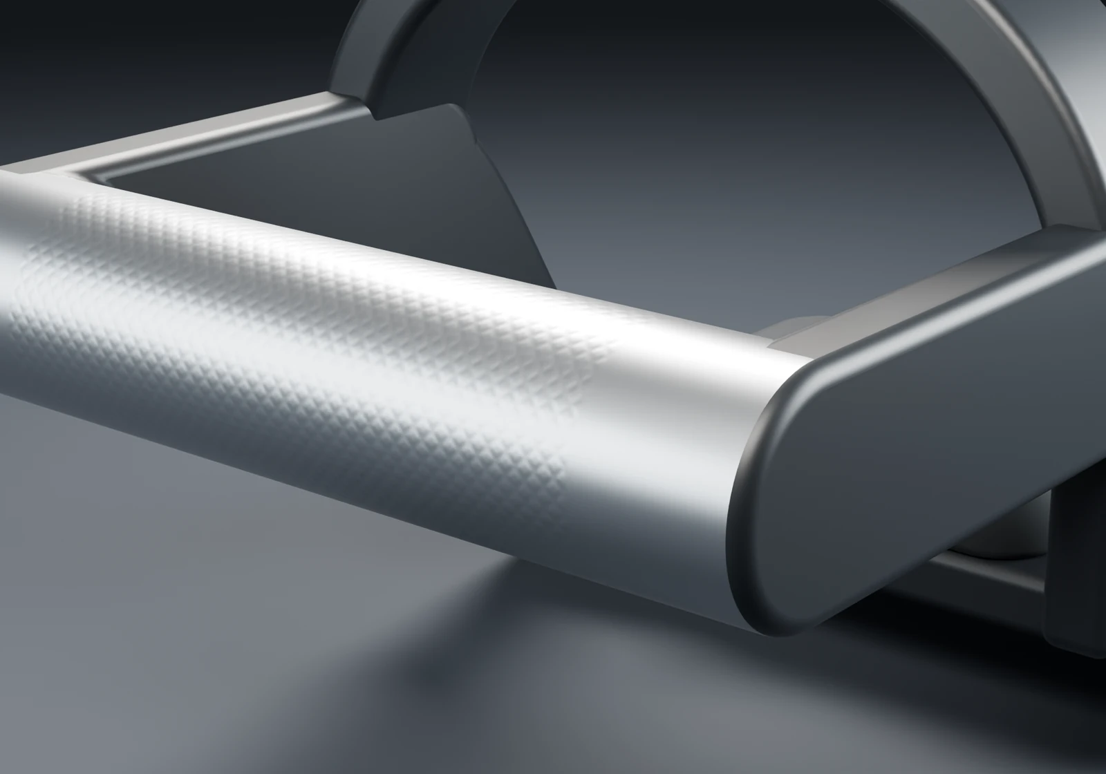
A solid Ø34 mm grip integrated into the frame, shown with a concept knurled finish. The bar sits deep in the palm, with four fingers tightly wrapped around it and an opposed thumb.
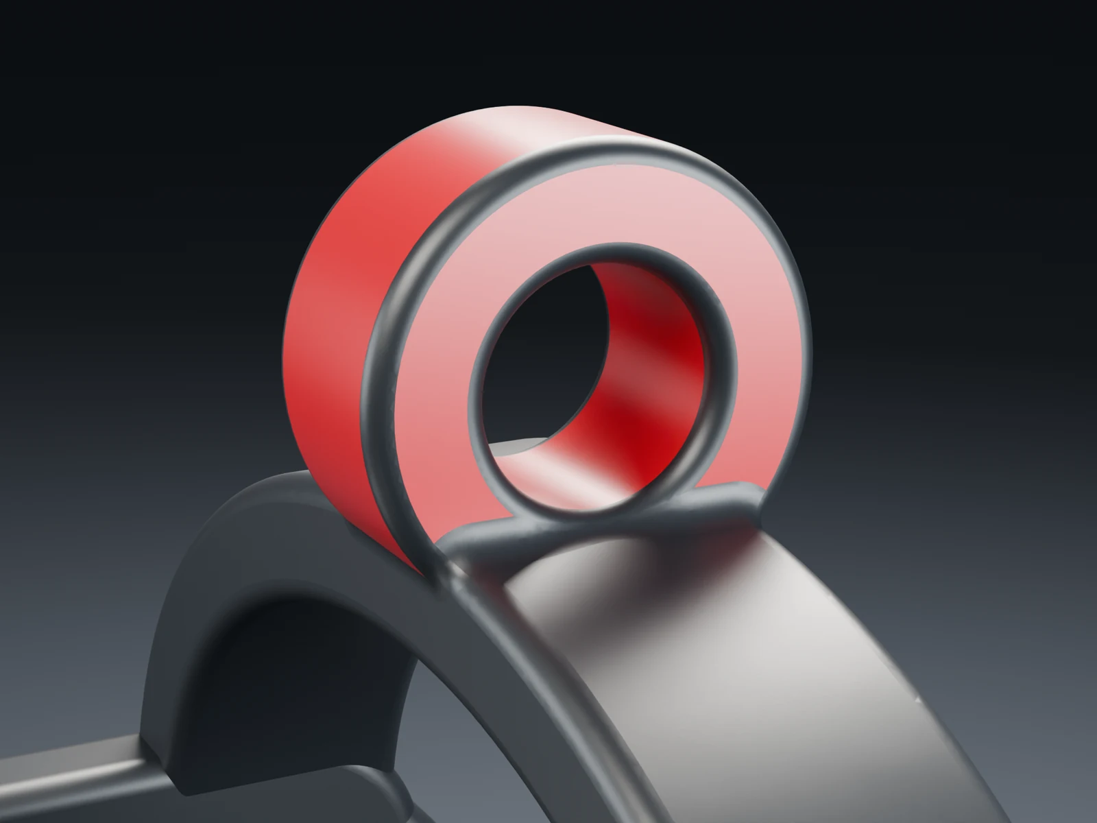
An open Ø20 mm eye merged directly into the arch. No tall neck between the eye and frame.
WEIGHT AND HANDLING
The metal model is calculated at approximately 3.69 kg using an assumed steel density of 8.0 g/cm³, before pad and connector. This is not a weighed physical specimen. Weight, balance, grip and contact pressure need to be assessed together before final material and manufacturing choices.
THE ENGINEERING / V3
Two metal geometries, the same cable force. Explore how V3 and an idealised D-shape carry the load, and compare stress, displacement and self-weight.
The same steel model and fixed grip. The D-reference is constructed without forearm support; it is not a measured competitor product.
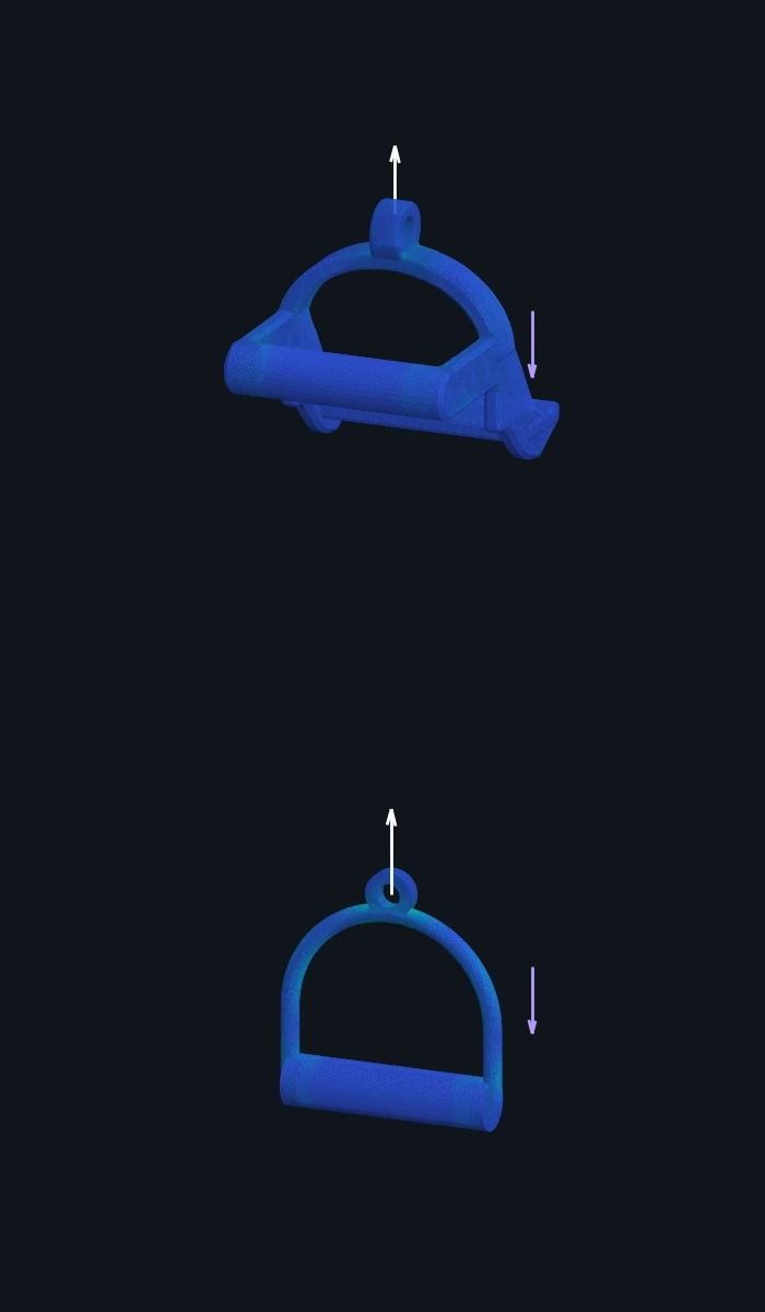
01 / STOAD V3
02 / IDEALISED METAL D
100 N · upward pull · including self-weight. ¹ Maximum at the model integration points, before element averaging. The force settings are calculation cases, not approved training loads.
Grip, side arms, arch and eye form one body. Rounded transitions replace decorative recesses in the load-bearing geometry.
This comparison restrains only the grip. The pad is free. How much load actually passes through the forearm requires contact analysis and physical measurement.
The solid grip and large body give V3 a high self-weight in steel. Mass, comfort and material use must be considered alongside stiffness before the design is finalised.
Linear elastic geometry comparison in CalculiX 2.23 using quadratic C3D10 tetrahedra. Both models use assumed isotropic steel: E = 200 GPa, ν = 0.30 and density 8,000 kg/m³. These are model inputs, not certified properties of a printed part.
V21 uses straight-sided C3D10 elements with quadratic displacement and faceted geometry. The volume difference from CAD is approximately 1.28%. The D-reference retains its curved C3D10 mesh. V3 mass comes from exact CAD, while self-weight is integrated over the mesh. This difference contributes to model uncertainty.
V3 uses the V21 geometry with a solid Ø34 mm grip. The D-reference has a hollow Ø34/28 mm bar, 140 mm total grip length, Ø12 mm frame and Ø32/16 mm eye with 10 mm thickness. All D-reference joints are assumed perfect. Welds, bearings, rotating grips and the connector are not modelled.
The outer grip surface over its central 100 mm is fixed in all three directions. Cable force is distributed over the upper or lower sector of the eye bore. Self-weight acts downward independently of cable force. Stress components are superposed before calculating von Mises. Both shapes use the same geometric and colour scales.
V3: 47,287 elements, 80,344 nodes, 1.283 % volume difference from CAD · D: 9,506 elements, 18,154 nodes, 0.017 % volume difference from CAD.
One illustrative mesh size per model; peak values have not been shown to be mesh-converged. Grip restraint and local geometry affect peaks. The model excludes yielding, fracture, fatigue, impact, print orientation, porosity and hand–pad contact. It therefore establishes no failure load, repetition count or service life. The earlier PLA prototype analysis is separate.
Download the calculation record · CalculiX · Material reference: Outokumpu Supra
THE MODEL IN NUMBERS
Designed as one continuous metal body for a single print build, without screws or end caps. A solid grip and rounded transitions. The soft padding is applied separately.
Nominal CAD dimensions. Clear width applies to checked sections above the floor radius; fit requires physical testing. ¹ At assumed steel density 8.0 g/cm³, before pad and connector.
We have a physical prototype. This page shows a revised digital fit candidate with support only at the distal forearm and a closed grip. Materials, production, pad retention, fit and strength require qualification before training use. No approved working load has been established. NOT FOR SALE.
Presentation name V3. Engineering revision V21_WIDE_CLEARANCE_STUDY. The physical specimen has not been measured against this revised geometry. The grip, side arms, arch and cable eye form one metal part. There are no separate screws, bolts or end caps. The eye is Ø40/20 mm and 20 mm thick. The 84 × 60 mm pad is centered 65 mm proximal to the digital wrist reference. This placement is an experimental target. The printer, build orientation, temporary supports and finishing still require qualification. A ten-year frame life is a development target requiring physical testing. The arch and eye are 20 mm lower. The support webs are 12 mm wide and extend further downward, giving a nominal 128 mm clear width in checked sections. The support floor is 156 mm wide. Overall width remains 156 mm. Decorative recesses have been removed from the load-bearing body. Metal geometry has been checked digitally. Renders show intended form and finish, and are not photographs of the specimen. Support meets only the distal forearm. The back of the hand and the wrist joint remain free. The contact surface is a digital fit study. Wrist unloading and a ten-year life have not been demonstrated. Self-weight must be included in the load assessment.